
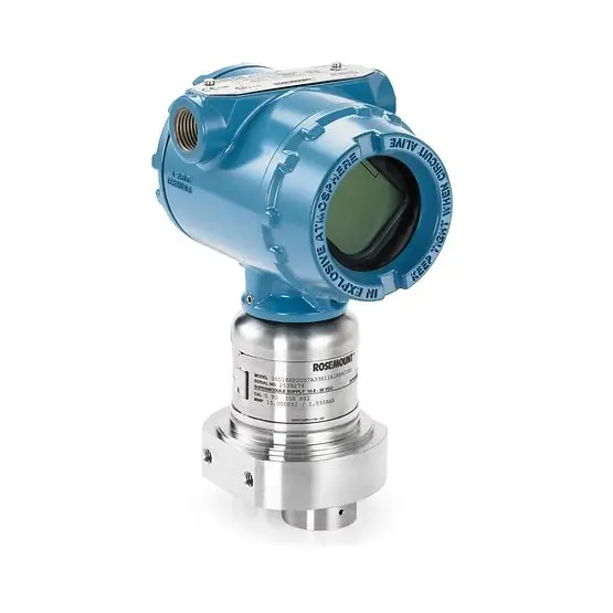
 Rosemount
 YokoGawa
 Yokogawa


Slurries are commonly used in many process industries, and measuring slurry flow rates is often challenging due to several reasons, including the varying sizes and volumes of entrained solids, density changes, laminar flow, and the typically high velocities required to keep the solids in suspension.
Common slurry measurement applications and challenges
Some common slurry measurement applications and challenges include:
- Pulp and paper: In the kraft process, the typical concentration of solids at the papermachine headbox is 3.6%. This is the most common process for producing chemical pulp, as it also produces stronger pulp than mechanical pulping.
- Metals and mining: Many slurries contain 5% to 8% solids, including high concentrations of over 50% solids in tailings lines at copper concentration plants.
- Chemical injection in oil, gas, and petrochemical products: Reactions in these applications can increase the noise in flow signals.
- Hydraulic fracturing applications: Accurate control of the water and sand mixture pumped into wells is required to within 0.25% to reduce the difficulty of downhole operations.
- Water and wastewater treatment brine: The high conductivity of brine, along with about 10% solids, results in highly variable flow measurements.
Fortunately, most slurries are water-based, making them conductive fluids that are well-suited for non-invasive flow measurement using magnetic flow meter or electromagnetic flow meters. This measurement technology is one of the few capable of measuring flow in both turbulent and laminar applications.
An electromagnetic flow meter consists of a transmitter and a sensor, which work together to measure flow. The sensor of the electromagnetic flow meter is placed inside the pipeline and measures the induced voltage generated as the fluid flows through the pipeline (Figure 1). The transmitter receives the voltage produced by the sensor, converts this voltage into a flow measurement, and transmits the flow measurement to the host system.
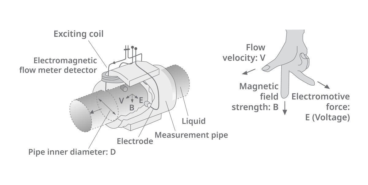
(1)A cross-sectional view of a magnetic flow meter and its indicator shows the velocity, magnetic field strength, and electromotive force (voltage), illustrating the elements of Faraday’s law of induction and their application in the magnetic flow meter.
Whether using electromagnetic flow meters (including those with an impact plate to protect the instrument liner and electrodes) to measure the flow of pulp, brine, or mining ores, particles in slurry flows can lead to unstable readings. This issue, along with others, can be addressed by carefully selecting the appropriate electromagnetic flow meter for each application.
Managing unstable signals in slurry flow measurement
Unstable and inaccurate readings in electromagnetic flow meters are often caused by debris carried in the fluid affecting electrode sensors and resulting in millivolt peaks interpreted as flow peaks. Glass fiber tubes are commonly used in brine or chemical services and often generate significant static electricity, similar to particle impact issues, which affect measurement integrity. With standard electromagnetic flow meters, these noise signals from electrode measurements are difficult to separate consistently and accurately from flow signals.
A traditional method to compensate for such noise is to extend the decay time of the flow signal, which is accomplished within the transmitter. Given the nature of these slurry signals, decay times of 30 to 60 seconds are not uncommon. While this technique can yield stable flow values, it is not conducive to real-time control. For many flow processes, the process dead time is often less than one second, so decaying to such an extent means responding to changes that occurred several cycles ago, potentially leading to unstable operation of control systems.
Such unstable operation often results in valve oscillation, reduced productivity, and downtime. Even with damping applied in both the transmitter and control system, noise levels are often too high to effectively regulate the process.
In one example at a pulp mill, the facility was forced to shut down automatic control entirely and operate control valves manually during the most severe problems, resulting not only in poor performance but also wasting operator time.
Better methods for measuring slurry flow velocity
One approach to reduce the impact of noise is to increase the available power of the signal generated by the sensor, such as increasing the power from the traditional design of 0.5 amps to 2 amps in newer designs. However, increasing signal power only addresses one aspect of measurement problems—noise signals—and does not fully address challenges posed by debris or other process-induced spikes.
Through analysis of over 200 real-world harsh environment noise samples during development and leveraging improved microprocessor capabilities, the magnetic flow meter development team identified the need for more sophisticated digital processing within the transmitter, including actively processing signals to identify and disregard anomalies caused by particle impacts.
Internal technology: Improvements in magnetic flow meters
This advanced transmitter is provided with new purchases of electromagnetic flow meters and can be retrofitted into existing devices (Figure 2). It includes three process noise curves, two coil frequencies, zero adjustment, and five preconfigured signal processing modes based on averaging time, process noise level, process noise coefficient/tolerance level, scanning time, and moving average time limits. There is also a fully customizable sixth “custom” signal processing mode to provide specific functionalities for applications. Technical support is available to assist with fine-tuning and developing custom configurations.
The instrument’s sensor (Figure 2, left image and Figure 3) features obstruction-free design with no moving parts, making it ideal for measuring conductive slurries and minimizing maintenance and repairs. Without moving parts or obstructions, there are no mechanical failures or material build-up, ensuring high reliability.
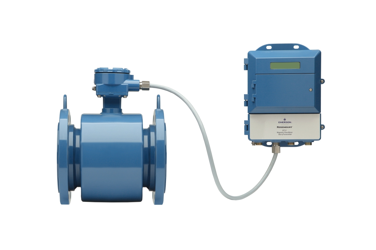
(2)The Rosemount 8782 slurry electromagnetic flow meter utilizes advanced signal processing technology to achieve accurate and stable measurements.
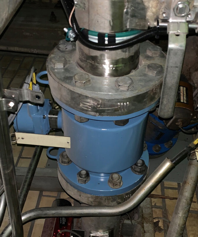
(3)The Rosemount MS magnetic sensor instrument is installed in slurry applications.
Advanced electromagnetic flow meters enhance accuracy, controllability, and throughput.
Across industries facing noisy electromagnetic flow meter signals, similar success stories can be found—significant improvements in accuracy, controllability, and throughput, particularly for slurries. Despite the ongoing challenges in slurry flow measurement, especially in highly conductive or abrasive environments, most of these applications can be addressed through modern electromagnetic flow meter technology.
The use of such cutting-edge technology in configurable and customizable ways reduces variability in flow readings, enabling operators to run plants closer to operational limits. It also provides improved automatic closed-loop control, better process stability, higher yields, and reduced equipment wear across various flow regimes, patterns, and velocities.
link to Product: Rosemount 8732E